5. Network representation: application resources
In the present section we will examine how network’s elements and topology are represented in SANET. For a general overview of Network Managament Systems design we suggest to refer to: Cisco’s “Network Management System: Best Practices White Paper”
Each network is composed of many elements which are generic entities to be monitored and managed [TODO riferimento ad articolo NMS]. Each network element provides one or more interfaces, physical or logical, which connects the pairs of elements.
But what is the best way to represent such entities, to classify them in order to perform all the moitoring tasks required, and to make management and monitoring issues easily accessible both to end users an network operators?
SANET defines some application entities, belonging to the abstract concept of resources, to accomplish these tasks.
Possible SANET resources are:
- Site: the global registry.
- Container: an arbitrary node holder.
- Node: the basic network element.
- Interface: connection endpoint associated to nodes.
- Target: check for a condition.
- Measure: retrieve and store a value.
5.1. The monitoring core: targets and measures
The whole monitoring system is based on periodical checks of given conditions, and information retrieval from network devices, server, and services that belongs to the network of interest.
SANET performs two kinds of controls which we call target and measure.
All controls are performed by the Poller process (look the Poller Documentation for more info).
5.1.1. Target
Targets are quality checks: they check if a retrieved value satisfies a condition within a specific amount of failure tolerance.
Each target is in a specific STATUS which can be:
- UP: if the retrieved value satisfies taget’s condition.
- FAILING: if the retrieved value does not satisfy the condition, BUT the amount of failures that happened is less than the amount of failure tolerance.
- DOWN: if the retrieved value does not satisfy the condition, AND it has excedeed the amount of failures tolerated
- UNCHECKABLE: if it is not possible to retrieve the value. It is possible to configure the control in order to make this status fallback to UP or DOWN state.
- INACTIVE: if the network operator suspended the target, i.e. he configured the system to not perform this check now. This is a configuration state.
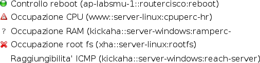
Possible target states (UP, FAILING, DOWN, UNCHECKABLE,INACTIVE)
As switching to UP or DOWN state happen, an email is sent to the configured mail recipient.
Take a look at Resource states to understand how target states are wrapped up and interpreted in their holder resources and contribute to determine the final resource status.
5.1.2. Measure
Measures are quantitative checks and are meant to act as value storage of retrieved informations, that are basically to be represented in graphs and help in the troubleshooting activity as soon as a DOWN target alarm is received.
They are also useful to predict the needs of hardware resources based on the analysis of the presented graphs. The classical example is given by noticing data growing and growing in disks and evaluate to buy some storage or a SAN. Another example can be the need of widening the bandwidth for a link which happen to be overloaded.
Retrieved values are stored in Round Robin Database (RRD) files that are presented in graphs that look like the ones presented by the widespread MRTG tool.
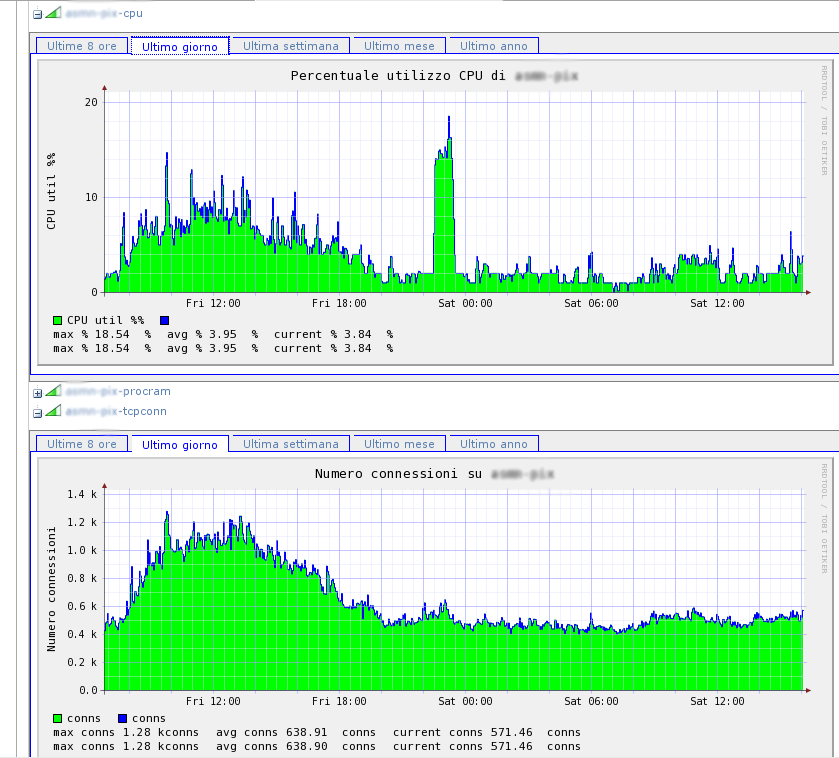
Example of measure graphs related to CPU load and amount of connections
5.2. Other resources: target and measure classification
SANET includes some other resources which act mainly as holders for targets and measures.
Each of the following resources directly or indirectly includes targets or measures and has its own status inherithed by the states of the targets that it holds. Resource states are computed by the following algorythm:
- UP : if and only if ALL included targets are UP.
- FAILING: if at least ONE target is FAILING or DOWN.
- DOWN: if ALL targets are DOWN. Nodes and interfaces are DOWN if their primary target is DOWN.
- UNCHECKABLE: if ALL of its active targets are UNCHECKABLE.
- INACTIVE: if ALL of its targets are INACTIVE.
A resource can also be displayed in its default icon colors which represents the status:
- UNAPPLIED: if the resource status has not been yet applied (it has still to be computed) or can’t be applied (case of multiple links shared by the same two endpoints in network maps)
Following the other kinds of resources will be described:
5.2.1. Network node
In general network node is the NMS basic network element. SANET network element is any real or virtual object that has one or more IPv4 or IPv6 address.
The figure Network element structure shows the internals of the network element which is bound directly to targets, measures and network interfaces. Network interfaces are in turn bound to their own targets and measures.
This logical representation makes SANET able to define specific controls for nodes and interfaces. In example for a node you would like to monitor the amount of RAM used or that a specific process is in execution, whereas for each interface you’d like to know its operating status (on or off), amount of transmitted and received data, amount of errors, etc.
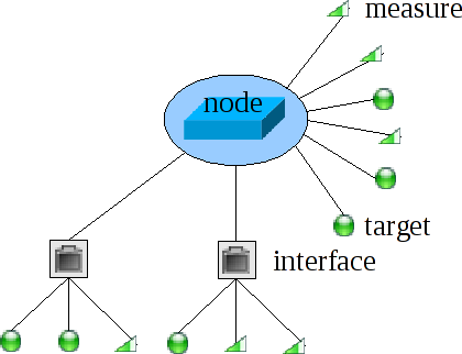
Network element structure
As you can see, targets and measures still remain the network monitoring core, but they are aggregated in the network nodes.
The node assumes a central role in classification of resources and can be interpreted in different ways:
- top-down : it aggregates targets, measures and interfaces
- bottom-up: it is the atom that can be classified in containers in order to produce desired network views.
5.2.2. Network interfaces and links
Network interfaces not only represent the aggregation of a series of checks, but they also have the fundamental role of link’s endpoint. In SANET links between nodes are expressed as link between interfaces, this allows to define a layer 2 representation of the network and to perform adiacency checks. Links are defined by human operator through the CLI, since according to SANET phylosophy the operator is required to know the network connections, hence he is in charge of explicitely defining the links to be monitored.
5.2.3. The site
Network nodes are included in the site, the global application registry. The site is the root starting from which all the resources can be reached. It holds global configuration parameters such as the name of the monitored network, the maximum number of threads to be used to perform checks, and the email watchdog addresses to be used for periodical update messages. This last feature is useful in the case where it is not possible to monitor the server itself through other SANET installations or alternative tools.
5.2.4. Container
Container is the resource type used to define nodes classification and to define various network views. Containers follow a tree-like structure, in an analogous way to the directories of a file system. Following the file system metaphore, nodes can be seen as files to be held in the directories. In SANET anyway classification is much more expressive than that, since nodes and containers hierarcies are customizable making it possible to define forest-like structures, rather than simple tree-like structures.
The general rule consists in each network node to possibli be be present in many containers belonging to different trees.
Each tree represents a classification typology, and each container represents a specific category. Usually trees are defined according to geographic location of the appliances, to responsibility hierarcy, or to the actual network topology.
The ability to put single nodes in different containers on different trees, basically translates into concepts as tagging or categorization typical of web 2.0 folksonomies. At the moment, the whole trees and containers structure configuration can be done using the CLI (CLI), hence it requires trained operators, but the policy adopted makes it possible to define views (trees and containers) suiting the final users desires.
Each container is bound to a network map which holds the information about nodes positions. See Network maps for more informations.
![]()